Last year i bought a cheap chinese prusa i3 clone for €270 including VAT and shipping which performs very good overall.
After assembling it – which took me about 8 hours – its print results was.. well.. quite okay.
As expected, because reading forums and blogs already explained Z wobble to be a serious problem with this printer.
So the first thing I’ve printed the already posted “Z wobble fix” which came out wobbly of course, but works well :)
I’ve also decoupled the Z axis from the frame by (gently) drilling a bigger hole in the top part of the printer so it can move freely.
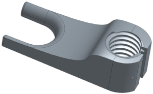
Then I also added a ball bearing (608Z) “decoupler” to the top end of the thread so it is not moving too much and is guided a bit better.
Aside of that, I replaced the too small Z axis rods with a proper one and the Z axis threaded rod with a TR8 trapezoid one.
After some printing, i wondered why the MOSFETs get so hot. They used P55NF06 with a quite okay R_DS(on) of 0.018 Ohms. But more problematic is the V_GS which is with 5V just barely above the threshold voltage.
This causes an resistance of far more than the 0.018 Ohms which you will only get at a V_GS of 10V. The result – the MOSFETs get hot.
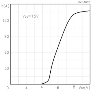
Solution? Buy some IRFB7430 which have only 0.001 Ohms R_DS(on) at 10V and ~0.013 Ohms at 5V.
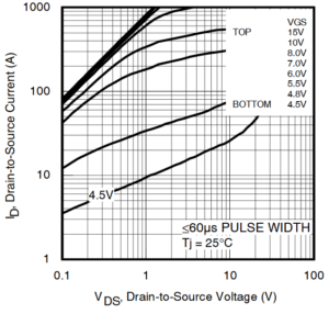
As these parts are a bit pricey, I’ve chosen to take the cheaper IRF2804 for the hotends. They still provide a low resistance with ~0.015 Ohms and are good enough for hotend heaters.
Probably also good enough for the heated bed :)
But..
before I was able to swap them, a really bad thing happened – my printer heated permanently until it smoked and i powered it off.
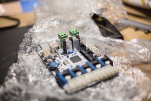
First let’s see how the GT2560 board looks like:
Now when looking at the heat sink of the MOSFET, one will realize that they have
a) a sharp corner
b) are electrically connected to the MOSFET with a metal screw and without any insulation pad
c) (no, you can’t see that on the photos) there is a PCB trace *exactly* below the sharp corner of the heat sink, prone to get scratched

After a while the PCB was scratched and the heatsink made a short circuit with a trace on PCB, permanently heating the hotend.
Yay. worst case. Even marlin’s “thermal runaway”-protection couldn’t do anything as they are short-circuited on board.
So the result was an overheated hotend with damaged PTFE inliner, died MOSFETs and me, a bit scared of this really bad engineering.
No fire tho, but there was smoke at least.
Okay to be honest, when paying 270€ for a whole box full stuff you can build a printer of, don’t be surprised if that is not at IBM quality level.
But there is a difference if a connector is of cheap quality or a rod is bent, or if a PCB designer doesn’t realize that a sharp-edged aluminum block just micrometers above a PCB trace that might cause malfunction and finally a fire is a frickin’ bad idea.
Solution:
a) now really buy the MOSFETs i already had chosen
b) along with insulation pads and plastic screws
c) and put some {glue, hot glue, epoxy, cyanacrylate, whatever} on the PCB below the heat sinks (i used a special solder mask pen)
d) put a smoke detector above the printer
Recommendation to all users of a GT2560: ALSO FIX THIS ISSUE, it might cause the printer to catch fire.
The wonderful side effect: you don’t need the devilish loud mainboard fan anymore.
After these changes, my printer works like a charm :)
It happened in october ’16 and geeetech sent me a second mainboard just days later so I could fix the other one properly.
(thanks for this really fast response and good service)
I hope this warning reaches out to all “cheap chinese printer” users out there.
